Lab 2
Realistic Camera Simulation
Due: Monday, November 21, 2016 at 23:59
This lab was modeled after the assignment 3 of Stanford's Image Synthesis class.- Individual Effort:
- No team participation is really encouraged in the case of the homework or the labs.
- Late Submission:
- In general late submission is not encouraged/accepted unless
there is a very good reason. You are encouraged to submit on time.
We are on a tight schedule. Being late for one lab could affect
the time left for you to complete subsequent labs. Late Submissions
are possible, yet they will be penalized.
- One day late: 15% penalty
- Two days late: 30% penalty
- Three days late: 50% penalty
- Four or more days late: 100% penalty.
Objectives
Most rendering systems generate images with the entire scene in sharp focus, mimicking a pinhole camera. However, real cameras contain multi-lens assemblies with finite apertures and exhibit different imaging characteristics such as limited depth of field, field distortion, vignetting and spatially varying exposure. In this assignment, you'll extend pbrt with support for a more realistic camera model that accurately simulates these effects. Specifically, we will provide you with specifications of real wide-angle, normal and telephoto lenses, each composed of multiple lens elements. You will build a camera plugin for pbrt that simulates the traversal of light through these lens assemblies onto the film plane of a virtual camera. With this camera simulator, you'll explore the effects of focus, aperture and exposure. Once you have a working camera simulator, you will add simple auto-focus capabilities to your camera.
Background Reading
Before beginning this assignment you should read the paper "A Realistic Camera Model for Computer Graphics" by Kolb, Mitchell, and Hanrahan. You may also want to review parts of Chapter 6 in pbrt.
Getting Started
Starter code and data files for Lab 2 are located here. In addition to source code, this archive contains the pbrt scene files you will render in this assignment, a collection of lens data files (*.dat), and auto-focus zone info files (*.txt).
In order to integrate the starter code into pbrt, please unpack the
archive into the root of your pbrt installation. You can do this by
first copying the archive to the root of your pbrt installation and
then by invoking the following command.
gunzip -c lab2_src.tgz | tar xf -
Modify pbrt
You'll need to make some modifications to pbrt before building the realistic camera class.
-
Add the following virtual method
to pbrt's Camera class in core/camera.h.
virtual void AutoFocus(const Scene* scene, const SamplerRenderer* sr, Sample* sample ) { }#include "renderers/samplerrenderer.h" -
Next, You'll need to call the AutoFocus method from
SamplerRenderer::Render
in renderers/samplerrenderer.cpp. immediately following
line sample allocation and just before the creation of renderer
tasks. The resulting code should look like this.
Sample *sample = new Sample(sampler, surfaceIntegrator, volumeIntegrator, scene ); camera->AutoFocus( scene, this, sample ); - Lastly, you'll need to make pbrt aware of the RealisticCamera class by calling the CreateRealisticCamera function from the MakeCamera function in core/api.cpp. You will also need to include the file cameras/realistic.cpp in core/api.cpp.
Building the Realistic Camera Class
At this point, you should be able to build the code simply by invoking make from the src/ directory. The Makefile provided with pbrt does not need any changes.
Browse the Code
In this assignment you will implement the RealisticCamera class defined in cameras/realistic.cpp. The other source files provided in the archive are helper classes that are useful when implementing auto-focus, and are discussed in the auto-focus section below.
Set Up the Camera
The pbrt scene files (in lab2scenes/ ) in this assignment specify that rendering should use the "realistic" camera plugin. The realistic camera accepts a number of parameters from the scene file including the name of a lens data file, the distance between the film plane and the location of the back lens element (the one closest to the film), the diameter of the aperture stop, and the length of the film diagonal (distance from top left corner to bottom right corner of the film). The values of these parameters are passed in to the constructor of the RealisticCamera class. All values are in units of millimeters. For example, a scene file might specify the following camera.
Camera "realistic"
        "string specfile" "dgauss.50mm.dat"
        "float filmdistance" 36.77
        "float aperture_diameter" 17.1
        "float filmdiag" 70
The .dat files included with the starter code (also in lab2scenes/) describe camera lenses using the format described in Figure 1 of the Kolb paper. The RealisticCamera class must read and parse the specified lens data file. In pbrt, a camera's viewing direction is the positive z-direction in camera space. Therefore, your camera should be looking directly down the z-axis. The first lens element listed in the file (the lens element closest to the world, and farthest from the film plane) should be located at the origin in camera space with the rest of the lens system and film plane extending in the negative-z direction. Each line in the file contains the following information about one spherical lens interface.
lens_radius z-axis_intercept index_of_refraction aperture
More precisely:
- lens_radius: the spherical radius of the element.
- z_axis_intercept: thickness of the element. That is, the distance along the z-axis (in the negative direction) that separates this element from the next.
- index of refraction: the index of refraction on the camera side of the interface.
- aperture: the aperture of the interface (rays that hit the interface farther than aperture/2 from the origin don't make it through the lens element).
Note that exactly one of the lines in the data file will have lens_radius = 0. This is the aperture stop of the camera. The maximum size is given by the aperture value on this line. The actual size of the aperture stop is given as a parameter to the realistic camera from the pbrt scene file. Also note that the index of refraction of the world side of the first lens element is 1 (it's air).
Generating Camera Rays
Next you'll need to implement the RealisticCamera::GenerateRay function. The GenerateRay function takes a sample position in image space (given by sample.imageX and sample.imageY) as an argument and should return a random ray into the scene. To the rest of pbrt, your camera looks just like any other camera; it just takes a sample position and returns a ray from the camera out into the world. Here's an outline of the main steps.
- Compute the position on the film plane that the ray intersects from the values of sample.imageX and sample.imageY
- Remember that the color of a pixel in the image produced by pbrt is proportional to the irradiance incident on a point on the film plane (think of the film as a sensor in a digital camera). This value is an estimate of all light reaching this pixel from the world and through all paths through the lens array. As stated in the paper, computing this estimate involves sampling radiance along this set of paths. The easiest way to sample all paths is to fire rays at the back element of the lens and trace them out of the camera by computing intersections and refractions at each lens interface (you will not be using the thick lens approximation from the paper to compute the direction of rays exiting the lens). Note that some of these rays will hit the aperture stop and terminate before exiting the front of the lens.
- GenerateRay returns a weight for the generated ray. The radiance incident along the ray from the scene is modulated by this weight before adding its contribution to the Film. You will need to compute the correct weight to ensure that the irradiance estimate produced by pbrt is unbiased. That is, the expected value of the estimate is the actual value of the irradiance integral. Note that the weight depends upon the sampling scheme you use.
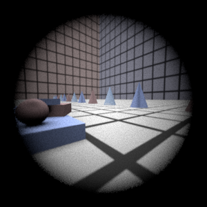
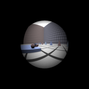
- Render each of the four scenes (lab2_dgauss.pbrt, lab2_wide.pbrt, lab2_fisheye.pbrt, lab2_telephoto.pbrt) using your realistic camera simulator. Example images rendered with both 4 and 512 samples per pixel are given below: telephoto (top left), double Gauss (top right), wide angle (bottom left) and fisheye (bottom right). Notice that the wide angle image is especially noisy -- why is that? Hint: look at the ray traces of Fig. 8 in the paper.
4 Samples Per Pixel


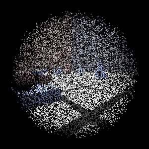
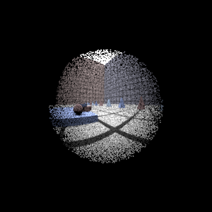
512 Samples Per Pixel
Note that the above images were rendered with an earlier version of pbrt.
The materials in your rendered images will look a little different since the
provided scene files use different materials.
Also, pbrt will generate warning messages about a scaling in the
camera-to-world transformation. You can safely ignore these messages.
Helpful Tips To Get You Started
- ConcentricSampleDisk() is a useful function for converting two 1D uniform random samples into a uniform random sample on a disk (see page 667 of the PBRT book.)
- You'll need a data structure to store the information about each lens interface as well as the aperture stop. For each lens interface, determine how to test for intersection and how to determine how rays refract according to the change of index of refraction on either side (review Snell's law).
For rays that terminate at the aperture stop, return a ray with a weight of 0 -- pbrt tests for such a case and will terminate the ray instead of sending it out into the scene.
- Be mindful of coordinate systems! Confusion between world space and camera space can be a major source of bugs. Also be wary of the fact that pbrt uses left-handed coordinate systems.
- As is often the case in rendering, your code won't produce correct images until everything is working just right. Try to think of ways that you can modularize your work and test incrementally. Use assertions liberally to verify that your code is doing what it should at each step. It may be worth your time to produce a visualization of the rays refracting through your lens system as a debugging aid (compare to those at Fig. 8 of the paper).
What You Need To Submit
You'll need to submit renderings for each of the four scenes at both 4 and 512 samples per pixel. You should also re-render lab2_telephoto.pbrt with the aperture radius decreased by half. What are the two main effects you expect to see? Does your camera simulation produce this result? By decreasing the aperture radius by one half, by how many stops have you decreased the resulting photographs exposure?
You should also submit a writeup which thoroughly describes your camera implementation and answers the following questions.
- What radiometric quantity is pbrt computing in your camera simulation? In other words: the color of each pixel in the output image is proportional to what quantity?
- Write an integral expression to compute the quantity described in question 1 at a point X on the film plane. Please precisely define all variables.
- Describe the domain of integration from question 2.
- Give the formula for F_n, a Monte Carlo estimator for the value of your integral. F_n is an estimate of the value of the integral using n samples drawn from the domain described in question 3.
- How did you draw samples from the domain of integration? Are you certain that you sampled from the space of all paths that light may have traveled through the lens? Describe the probability distribution used to generate random samples.
- Describe how pbrt computes F_n using your RealisticCamera class.
Auto-Focus
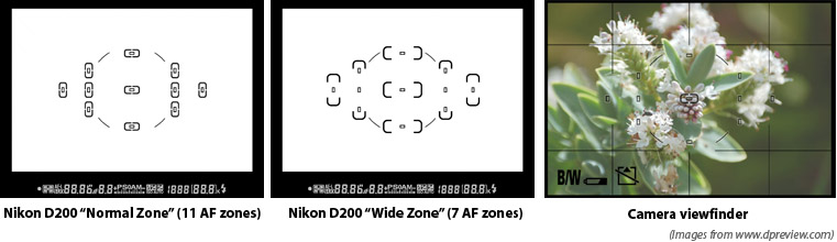
The auto-focus mechanism in a modern digital camera samples light incident on subregions of the sensor (film) plane and analyzes light in these subregions to compute focus. These regions of the frame are called auto-focus zones (AF zones). For example, an auto-focus algorithm might look for the presence of high frequencies (sharp edges in the image) within an AF zone to determine that the image is in focus. You may have noticed the AF zones in the viewfinder of your own camera. As an example, the AF zones used by the auto-focus system in the Nikon D200 are shown below.
In this part of the assignment, you'll be implementing an
auto-focus algorithm for your RealisticCamera. We will
provide you a scene and a set of AF zones, and you will need to use
these zones to automatically determine the film depth for your camera
so that the scene is in focus. Notice that in
lab2_afdgauss_closeup.pbrt, the camera description contains an
extra parameter af_zones. This parameter specifies the text file that
contains a list of AF zones. Each line in the file defines the bottom
left and top right of a rectangular zone using four floating point
numbers:
xleft xright ytop ybottom
Implementing Auto-Focus
You will now need to implement the AutoFocus method of the RealisticCamera class. In this method, the camera should modify its film depth so that the scene is in focus.
There are many ways to go about implementing this part of the assignment. One approach is to shoot rays from within AF zones on the film plane out into the scene (essentially rendering a small part of the image) and then analyze the subimage to determine if it is in focus. The starter code provided is intended to help you implement auto-focus in this manner. Here are some tips to get started with the provided code:
- The provided CameraSensor class (defined in film/camerasensor.h) is similar to the pbrt Film class but does not write data to files and can be cleared using the Reset() method. You can use this class to produce subimages corresponding to each AF Zone. The CameraSensor::ComputeImageRGB() method will return a pointer to an array of floating point RGB values suitable for analysis.
- SimpleStratifiedSampler (defined in samplers/simplesampler.h) is a modified version of PBRT's stratified sampler that is adapted for the needs of this project. Unlike pbrt's samplers, the SimpleStratefiedSampler can be reset and reused multiple times.
- Take a look at the "Sum-Modified Laplacian" operator described in Sree Nayar's "Shape From Focus" paper as an example of a sharpness heuristic.
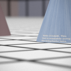
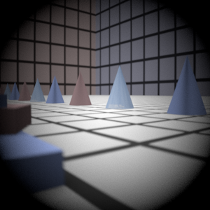
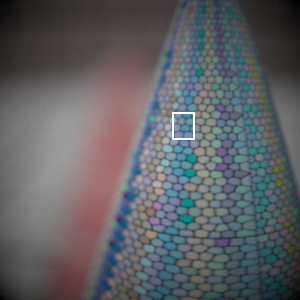
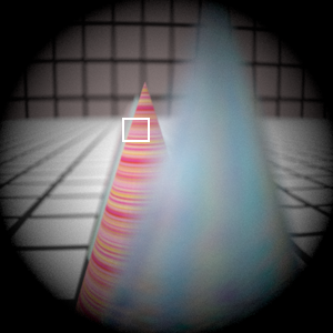
To test your auto-focusing algorithm, we provide three scenes that require the camera to focus using a single AF zone. The images resulting from proper focusing on lab2_afdgauss_closeup.pbrt, lab2_afdgauss_bg.pbrt, and lab2_aftelephoto.pbrt are shown below (rendered at 512 samples per pixel). The location of the AF zone in each image is shown as a white rectangle.

Fancier Auto-Focus (Not Required)
We have also provided scenes lab2_afspheres.pbrt and lab2_bunnies.pbrt that are constructed so that there is a choice of which object to bring into focus. We have defined multiple auto-focus zones for these scenes. How might you modify your auto-focus algorithm to account for input from multiple zones? Many cameras choose to focus on the closest object they can bring into focus or have "modes" that allow the user to hint at where focus should be set. For example, you might want to add an additional parameter to your camera that designates whether to focus on close up or far away objects in the scene.
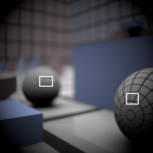
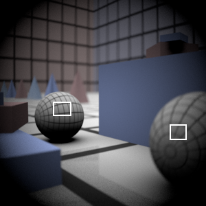
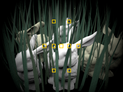
Note that the spheres scene uses different material properties, so your images will look a little different. The bunnies scene is unaltered.
Additional Hints and Tips
- When generating subimages corresponding to the AF Zones, it will be important that you use enough samples per pixel to reduce noise that may make it difficult to determine the sharpness of the image. By experimentation, we've found that 256 total samples (16x16) using the Sum-Modified Laplacian gives stable results.
- Although the auto-focusing approach described here involves analyzing the image formed within each AF zone, an alternative approach would be to compute an initial estimate of focus using the depth information of camera ray intersections with scene geometry. Using the thick lens approximation from the Kolb paper, you might be able to compute focus more efficiently than the approach described above.
- Note that the CameraSensor contains (commented out) code to dump the current image to disk. This can be very useful in debugging.
- Challenge! See how fast and how robust you can make your auto-focusing algorithm. How might you minimize the number of times you re-render a zone? How can you limit the range of film depths you search over? Can you think of better heuristics than the Sum-Modified Laplacian to estimate sharpness?
What You Need To Submit
Please submit renderings for lab2_afdgauss_closeup.pbrt, lab2_dgauss_bg.pbrt, and lab2_aftelephoto.pbrt at the film depth computed by your auto-focus routine with at least 256 samples per pixel.
In addition, please add a description of your auto-focus implementation and the film plane depths your algorithm computed for each of the three scenes to your writeup.
Submission
Be sure to double check your final submission by unzipping it in another directory on a computer in the PC LAB and testing it. (Especially for last minute submissions.) A project that doesn't run will lose more points than one that is one day late. Be sure to submit any comments or remarks in a 'readme.txt' file. Submit your files at Moodle here. Your submission should contain:- Include one paragraph about the estimated effort you put into this lab. How many (focused) hours of work did it take you and roughly where did you spend most of your time.
- A detailed description of your camera implementation and auto-focus algorithm. Be sure to let us know what you tried, what worked well, and what did not work so well. Also describe how you chose to sample paths of light incident on the film through the lens.
- Your camera implementation code (realistic.cpp and all other files you added or modified) in a single zip file attachment.
- All the images listed in the "What to Submit" sections in the steps above, clearly labeled, attached and embedded in the page.
- Answers to questions listed in the "What to Submit" sections in the steps above.
- Also, feel free to submit any other cool images you generate.
All files should be contained in a single ZIP file. Make sure your code, images, and report, are contained in their own, separate folders within the ZIP file.
We expect a good student to have to work approximately 20 hours on this assignment.
Grading
This assignment will be graded on a 4 point scale:
- 1 point: Significant flaws in camera simulation
- 2 points: Camera simulation works (or contains minor flaws), no implementation of auto-focus
- 3 points: Code correct but writeup does not address all points listed above
- 4 points: Code correct and a clear, complete writeup
- Optional: We are happy to give extra credit for exceptional experimentation!
NOTE: We will NOT (under any circumstance) accept labs that only run under windows or have porting problems. You are on your own, if you use windows to develop your labs. There will be absolutely NO exceptions.