Lab 1
Studio Lighting
Due: Thursday, October 26, 2016 at 23:55
Start Early!!!
This lab was modeled after the assignment 1 of Stanford's Image Synthesis class.- Individual Effort:
- No team participation is really encouraged in the case of the homework or the labs.
Objectives
This assignment helps you familiarize yourself with PBRT, the physically based rendering toolkit, and prepare for the future lab assignments. You will experiment with different scene settings and parameter combinations.
Step 1: Building PBRT
Please download the pbrt-v3 code from the PBRT website
in the Downloads section.
A large collection of pbrt-v3 scenes are also available in the Scenes
section. If you download the repository snapshot as the .tar.gz file, you might
need to receive the scene files from the repository with the following commands:
git checkout . && git pullYou can also download individual models from Benedikt Bitterli's rendering resources web page.
To create the makefile or Visual Studio project, you need to install CMake first. You can find detailed instructions for setting up and compiling the PBRT here. Alternatively, you can follow these instructions:
- Create a folder for the build files in the pbrt's root folder:
/path/to/pbrt-v3/build/ - Go to the build folder:
cd build -
Run CMake to create the proper make files. You can find CMake's parameters by
cmake --helporcmake /?- on Windows:
cmake .. -G "Visual Studio 15 2017 Win64" - on MacOS:
cmake .. -G "Xcode" - on Windows:
cmake .. -G "Unix Makefiles"
- on Windows:
-
Now the Makefiles or the project files are created by CMake. You can open the project
files (e.g.
pbrt-v3.slnfor Visual Studio), or directly make the binaries by callingmake -j4on Linux/MacOS ornmake /j4on Windows. The switch "-j4" runs the make command with 4 parallel threads. -
The final executables are ready in
binfolder orReleaseorDebugfolder depending on your compile mode. We will use thepbrtandimgtoolcommands regularly.
To be able to call the pbrt command from any folder, you can add it's address
to the path environment variable. On Linux/MacOS, it is done by:
export PATH=/path/to/pbrt/bin/:$PATHpbrt command.
Step 2: Rendering Your First Image
Once the compilation is done, you can render your first image. The starter files can be downloaded here. After you unzip the folder, you can render the image with this command:
pbrt lighting.pbrtAfter the rendering is done, it will print out the rendering statistics and the image will be stored in
lighting.exr file. The name of the output image is specified in the input
lighting.pbrt file, as a parameter in the Film definition. You can pass
different filenames with other extensions (e.g. png or jpg) and pbrt will automatically determine
the encoding from the file extension. The EXR image has a high dynamic range (HDR) format and
stores linear radiance values, which can have a very large range, beyond the range that your screen
can handle. Several image processing/viewing tools can do the conversion automatically (e.g.
OS X's Preview, Adobe Photoshop, GIMP 2.9.2+, OpenEXR exrdisplay). PBRT has a built in tool for
this conversion, called imgtool. You can convert the image to the png format using
this tool:
imgtool convert lightings.exr lighting.png
Please always convert your output images to png using imgtool before submitting it, unless
specified otherwise.
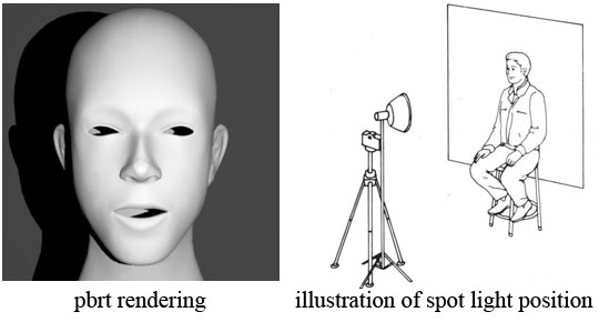
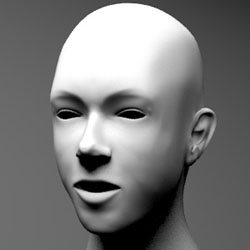
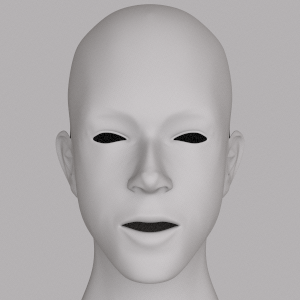
A correctly rendered image is shown above on the left. The scene setting is shown on the right side, where the camera is pointed directly at the model of a face. A spotlight shines on the face from behind the camera and slightly off right, casting hard shadow on the wall behind the model. The location of the camera and spotlight are illustrated in the image.
Before moving on to the rest of this assignment, please open the lighting.pbrt file with
your favorite text editor and go through the model and the comments around them. Try to understand the
camera parameters and the head model. Keep in mind that pbrt uses a left-handed coordinate system.
It is also highly recommended that you take some time to go over Camera, Lights, and Area Lights in
the pbrt-v3 file format manual before you start
modifying the scene file.
Changing Rendering Parameters
The image properties are defined in the scene file under the Film definition:
Film "image" "string filename" ["lighting.exr"]
    "integer xresolution" [300] "integer yresolution" [300]
Beside the filename and extension, you can also change the image resolution with
integer xresolution and integer yresolution parameters. Notice that the parameter
type is always specified before the name in pbrt scene file format.
The image resolution has a direct effect on the rendering speed. So, you can reduce the resolution in your tests if you want faster rendering when playing with parameters but you should submit your images with the original resolution of 300x300
Another factor that affects the rendering speed is the number of samples (eye rays) that pbrt uses to
compute the value of each output pixel. The Sampler definition in the scnee file is:
Sampler "halton" "integer pixelsamples" [4]Please submit your images with at least 4 samples per pixel unless mentioned otherwise. In your own experimentations, you can change this parameter to increase the rendering speed.
Step 3: Lighting the Scene
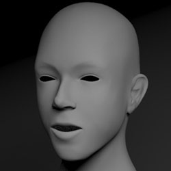
For the rest of this assignment, we will try several different lighting configurations.Configuration 1: Spotlight from Below
In this configuration, we will move the spotlight so that it points up the face from below. To do so, you will need to modify the spotlight parameters inlighting.pbrt file, in the spotlight
section:
LightSource "spot" "color I" [50 50 50] "point from" [-0.5 0 4.7]
    "point to" [0 0 0] "float coneangle" [60]
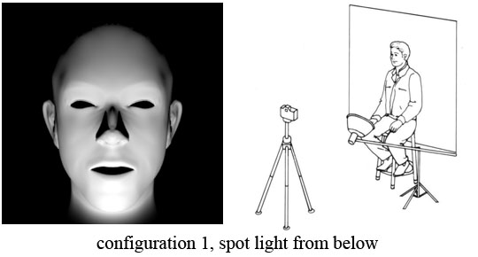
point from and point to parameters
of the spotlight to create the lighting above.
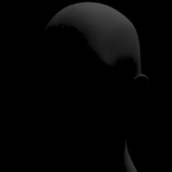
Configuration 2: Area Lighting from the Right
The light generated by a spotlight originates from a single point. Light that is originated from a single point or a small area creates hard shadows that photographers generally find visually objectionable. Area lights can emit light from a larger region in space, resulting in a softer lighting of the object and a shadow with penumbra. The pbrt scene file contains the following definition of an area light, which is originally commented out:AttributeBegin
AreaLightSource "area" "color L" [10 10 10]
# use camera coordinate system [optional]
CoordSysTransform "camera"
# adjust light source position
Translate 0 0 -2
Rotate 90 1 0 0
# define the shape of the arealight to be a disk with radius 1.5
Shape "disk" "float radius" [1.5]
AttributeEndLight from this source is emitted from a disk of radius 1.5. Comment out the light from configuration 1 and modify the area light above to generate the picture below:

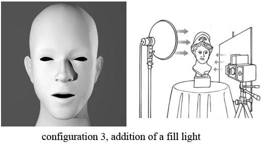
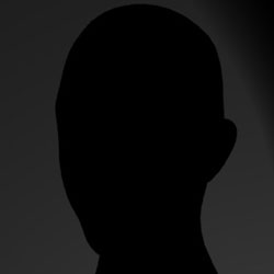
Configuration 3: Two Light Sources
Photographers usually use a reflecting surface on the opposite side of the light to prevent the object's shadow on itself and have a more uniform lighting of the model. The second source of light on the model is referred to as fill lighting. We model this effect in this assignment by using two light sources. Illuminate the model with a spotlight from the position indicated in the illustration below. Then use a large area light on the right of the model to give the effect of fill lighting on the dark side of the face. Render the scene with and without the fill lighting to observe the visual differences.
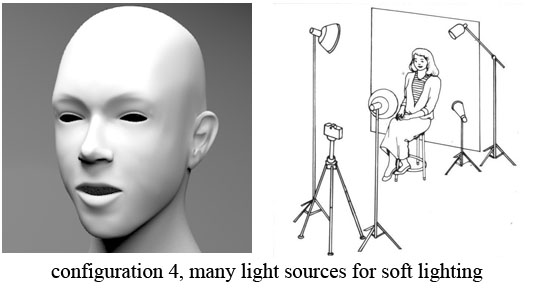
Configuration 4: Many Light Sources
In practice, photographers use many lights to illuminate a subject so that the resulting image conforms
precisely to their preferences. Try to adjust the lighting condition to recreate the scene below, in
which four light sources are used to create a visually pleasing effect. You will also need to move the
camera for this configuration. The LookAt directive specifies the position of the camera in
world space, the location it is pointed at, and the "up" direction of the camera. Camera settings are
defined in the scene file by the following two lines:
LookAt 0 0 4.5  0 0 0   0 1 0
Camera "perspective" "float fov" [22]
 |
The main light on the side of the face, away from the camera. |
|---|---|
 |
The fill light close to the camera on the opposite side from the main light. |
 |
The accent light shines towards the upper part from the back of the subject. Normally, it is used to highlight the texture of hair; or lack of hair in our case. |
 |
The background light separates the subject from the background. It is placed behind the subject and to one side, facing toward the backdrop. |
Configuration 5: Realistic Lighting
Manually placing lights is a time consuming process and not very efficient in recreating the real environment. A popular technique to overcome this issue is to use a HDR "environment map" as a light source for the rendering. The environment map has captured light from all directions in a real-world environment and can simulate a real world lighting for our model. The following environment map is provided for you in the assignment's zip file, at textures/doge2_latlong.exr:
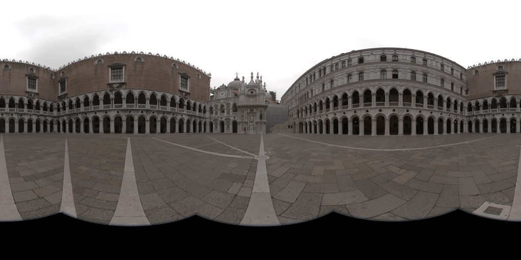
The necessary configuration line is already in the scene file as:
LightSource "infinite" "string mapname" ["textures/doge2_latlong.exr"]Uncomment out the environment map light and comment out all other light sources to generate the following image:
You will need to increase the pixelsamples of the Sampler significantly to get an image with a small amount of noise. Please use at least 64 samples per pixel for this configuration. This brings up an interesting trade-off that you can see everywhere: We were able to drastically simplify the amount of work that needs to be done by humans by making the computer work harder.
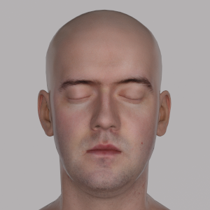
Configuration 6: Realistic Model and Materials
We have a more realistic model of the head geometry at geometry/head.ply, which can be textured as a human face by an image from textures/head_albedomap.png in the assignment's zip file. To change the model with the realistic model, comment out the "Head model" section in the scene file and uncomment the "More realistic head model" section. You might need to increase the pixelsamples again. You can also change the maxdepth parameter of the Integrator to capture the reflections of the light on the model itself. The following image was created using 4096 samples per pixel with maximum depth of 5. Since it might take a long time to render with these parameters, you can submit an image with any settings that has more than 64 samples per pixel and maximum depth greater than 3.
Step 6: Submission
Be sure to double check your final submission by unzipping it in another directory on a computer in the PC LAB and testing it. (Especially for last minute submissions.) A project that doesn't run will lose more points than one that is one day late. Be sure to submit any comments or remarks in aREADME.TXT file.
Submit your files on Moodle here.
You only need to submit your solutions for the configurations in Step 3.
Submit everything in a ZIP file that contains:
- A text file called
EFFORT.txtthat includes one paragraph about the estimated effort you put into this lab; How many (focused) hours of work did it take you and roughly where did you spend most of your time. - The source file for each configuration. Each file should be named as
lighting_<CONFIG>.pbrt. For example, the scene file for the configuration 5 should be submitted aslighting_5.pbrt - Images for each configuration. Please name them as
<CONFIG>_<NUM>.png. For example, if you are submitting two images for section 3, configuration 4, the images should be named as4_1.pngand4_2.png. - All images should be rendered with 300x300 resolution and at least 4 samples per pixel. For configurations 5 and 6, you need at least 64 samples per pixel for the submitted images.
We expect a good student to have to work approximately 8 hours on this assignment.
Academic Honesty